
Time-Resolved Photoluminescence (TRPL)
Introduction to Time-Resolved Photoluminescence (TRPL)

Figure 1. Jablonski diagram of radiative and non-radiative relaxation pathways, and schematic of time-correlated photon detection. After excitation by a pulsed laser, excited electrons relax through radiative and non-radiative pathways before returning to the ground state. Each radiative process emits photons with a characteristic delay relative to the excitation pulse. By time-stamping the laser synchronization signal and detected photons, the Time Tagger reconstructs a histogram of photon arrival times that reveals the photoluminescence decay dynamics. (VR: vibrational relaxation; ISC: intersystem crossing; rISC: reverse intersystem crossing; TA: thermal activation.)
Time-resolved photoluminescence (TRPL) measures the temporal decay of photoluminescence emission following pulsed optical excitation, from which excited-state lifetimes are extracted by fitting the decay dynamics. By tracking how photoexcited states relax back to the ground state, TRPL resolves the underlying relaxation pathways, as shown in Figure 1. Each pathway proceeds on a characteristic timescale, so the distribution of measured lifetimes acts as a signature of the underlying processes in the sample. Radiative recombination is observed via emitted photons, while non-radiative channels are inferred from their effects on decay dynamics. This makes the lifetime histogram a sensitive diagnostic tool: defects, impurities, and interfaces introduce additional decay components that appear as distinct time constants.
The extracted lifetimes report on charge-carrier dynamics, trap and defect activity, and recombination pathways. Unlike steady-state photoluminescence, which captures spectral intensity at equilibrium, TRPL resolves the time domain, enabling the identification of multi-exponential decays from coexisting species, distributed lifetimes in disordered systems, and competing non-radiative processes such as carrier diffusion to interfaces or energy transfer to acceptors 1 2. These capabilities make TRPL a key characterization technique in semiconductors, perovskites, organic emitters, quantum dots, and other photonic materials 3 4. The extracted lifetimes guide material optimization by revealing defects, trap states, surface recombination, and charge-transfer processes.
Experimental Setup for TRPL Measurements and the Role of Timing Electronics
Time-resolved photoluminescence (TRPL) setups combine a pulsed excitation source, efficient photon collection optics, and timing electronics that record photon arrival times relative to the excitation pulse 1. Figure 2 sketches a typical setup that includes:
- Excitation and triggering: An ultrafast pulsed laser excites the sample at a defined repetition rate, which can be driven by a pulse generator such as the Pulse Streamer. A synchronization output provides the timing reference for data acquisition. The repetition rate must be chosen such that emission from successive pulses does not overlap, avoiding pulse pile-up effects.
- Sample and collection optics: The excitation beam is focused onto the sample using free-space optics or a microscope setup. Emitted photoluminescence is collected, spectrally filtered to reject laser light, and directed either in free space or via fiber to the detector.
- Photon detection: Emitted photons are detected using single-photon detectors such as photomultiplier tubes (PMTs), single-photon avalanche diodes (SPADs), or superconducting nanowire single-photon detectors (SNSPDs).
- Data acquisition and analysis: The detector signal and laser synchronization signal are time-stamped by timing electronics and recorded as event streams. Photon arrival times can be referenced to a synchronization signal or stored as continuous timestamp data with picosecond resolution. Decay histograms are reconstructed in software, enabling flexible analysis across multiple channels and measurement types.
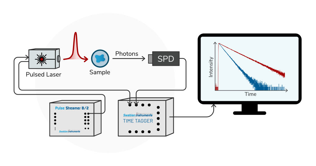
Figure 2. Schematic of a time-resolved photoluminescence (TRPL) setup. A pulsed laser excites the sample, and the emitted photons are detected by a single-photon detector (SPD). The laser trigger and photon detection events are time-stamped to construct a histogram of photon arrival times relative to the excitation pulse, yielding the photoluminescence decay curve.
Common Challenges in TRPL due to Conventional Timing Electronics
Accurate TRPL measurements depend on precise timing between excitation and detection. Several system-level effects influence the achievable time resolution and measurement stability.
- Timing Jitter: TTRPL experiments require picosecond-level timing resolution to accurately resolve fast decay dynamics. Timing jitter from the detectors, TDC, and laser synchronization signal broadens the instrument response function (IRF), reducing decay-curve sharpness and limiting the ability to distinguish fast or overlapping recombination processes. As material systems become more complex, high timing fidelity becomes essential for resolving multi-exponential decay behavior.
- Timing Drift and Clock Locking: Locking the timing electronics to the laser repetition rate can prevent slow relative drift between the laser and the instrument’s internal oscillator, an effect that otherwise shows up as a gradual shift of the lifetime histogram and artificial broadening over long acquisitions. Many TCSPC and TDC systems require external reference clocks at specific standard frequencies (often 10 MHz), which creates integration constraints with laser repetition rates. In these cases, locking to the laser is often not directly possible with standard timing electronics.
- Sequential, Single-Purpose Measurements: A complete characterization of a photonic material or quantum emitter rarely reduces to a single decay histogram. Researchers routinely also need the photon count rate and the second-order photon correlation function to verify single-photon emission, often across several detection channels. Conventional systems handle one measurement at a time, so accessing a different observable means stopping the acquisition, reconfiguring the setup, and remeasuring, a workflow that is slow and unreliable whenever sample conditions drift between runs.
Swabian Instruments’ Time Taggers for Optimized TRPL Experiments
Swabian Instruments’ Time Taggers are data acquisition systems for precise time-correlated experiments, engineered to meet the highest requirements of time-resolved photoluminescence (TRPL) measurements through a unique combination of powerful hardware and a flexible software platform.
- Low Jitter: Time Taggers feature intrinsic timing jitter down to 1.5 ps (RMS), reducing the contribution of timing electronics to the instrument response function (IRF). By minimizing internal timing uncertainty, electronic timing limitations are significantly reduced, and the IRF is typically dominated by the detector response.
- Software-Defined Frequency locking: The ReferenceClock functionality of the Time Tagger software implements a software PLL that rescales time tags on the fly to this reference, averaging down timing noise and keeping analysis phase-aligned, even when a Conditional filter is enabled on the laser channel.
- Concurrent Multi-Channel Measurements: The Time Tagger records detected photon arrival events across all channels onto a single shared time base, so that one continuous stream can feed multiple measurement engines at once. Photoluminescence lifetimes, photon count rates, and second-order correlation functions can all be computed concurrently from the same acquisition, without the need to stop or reconfigure the measurement, so every observable describes the same sample state. On-the-fly data filtering extends this further: photon streams can be gated or conditionally filtered in real time before being routed into any downstream measurement, rather than requiring a separate post-processing pass.
- Powerful yet intuitive software engine: Swabian Instruments offers a comprehensive Software Development Kit (SDK) with an extensive API in common programming languages (Python, MATLAB, LabVIEW, C#, and C++) for seamless automation and integration with existing experimental setups. The intuitive GUI of Time Tagger Lab enables the setup of a lifetime decay experiment in just a few clicks.
Time-resolved photoluminescence (TRPL) experiments rely on precise timing between excitation and detection to resolve photoluminescence decay dynamics across a wide range of materials. The main limitations in conventional systems arise from the combined instrument response function, long-term timing drift, and restricted measurement workflows. Swabian Instruments’ Time Taggers address these challenges through continuous timestamp acquisition, software-based synchronization, and flexible multi-channel analysis, enabling stable and flexible TRPL measurements.
Fluorescence Lifetime Imaging (FLIM)
Discover fluorescence lifetime imaging (FLIM), a powerful imaging technique for mapping fluorescence lifetimes with picosecond precision. Learn how Swabian Instruments' Time Taggers enable high-resolution FLIM measurements using advanced timing electronics, supporting detectors like PMTs, SPADs, and SNSPDs for cutting-edge research applications

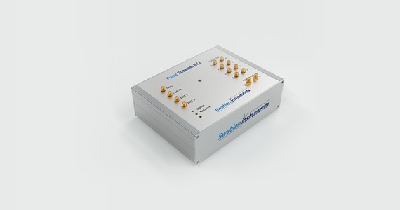
Pulse Streamer 8/2
The Pulse Streamer 8/2 is a synchronous digital pattern and arbitrary waveform generator with 8 digital and 2 analog output channels.
Read moreM. Cannas and L. Vaccaro. “Time-resolved photoluminescence,” in Spectroscopy for Materials Characterization, ed. S. Agnello, Wiley, Hoboken, ch. 2 (2021) ↩︎ ↩︎
J. A. Peters, et al. “Carrier recombination mechanism in CsPbBr₃ revealed by time-resolved photoluminescence spectroscopy.” Phys. Rev. B 100, 235305 (2019). ↩︎
P. Y. Yu and M. Cardona. “Fundamentals of Semiconductors: Physics and Materials Properties”, 4th ed., Springer, Berlin, pp. 160–182, 349, 369–371 (2010). ↩︎
D. W. deQuilettes, S. M. Vorpahl, S. D. Stranks, H. Nagaoka, G. E. Eperon, M. E. Ziffer, H. J. Snaith, D. S. Ginger. “Impact of microstructure on local carrier lifetime in perovskite solar cells.” Science Volume 348, Issue 6235, pp. 683–686 (2015). ↩︎