Hardware
Operating conditions
Before installing and operating the Time Tagger, users are strongly advised to follow the guidelines for proper handling. For detailed information on the operating conditions of the Time Tagger, please consult the section Safety & Compliance.
Input channels
The Time Tagger has 8, 18, or 20 inputs (SMA-connectors) for Time Tagger 20, Time Tagger Ultra, or Time Tagger X, respectively. The electrical characteristics are tabulated below. Each input can detect both, rising and falling edges of an input pulse, and each input has two channels associated with it. Rising edges correspond to channel numbers 1 to 8, 18, or 20 for Time Tagger 20, Time Tagger Ultra, or Time Tagger X, respectively; and falling edges correspond to respective channel numbers -1 to -8, -18, or -20 for Time Tagger 20, Time Tagger Ultra, or Time Tagger X, respectively. Thereby, you can treat rising and falling edges in a fully equivalent fashion.
Note
Time Taggers delivered before mid-2018 were labeled using a legacy 0-based channel numbering scheme. The table below shows the legacy channel numbering scheme used by software versions up to v2.21.x. It is kept here as a reference for users interpreting older hardware labels or maintaining older code. Starting with v2.22.0, only the default 1-based scheme is supported, with rising edges numbered from 1 to N and falling edges from -1 to -N. Users upgrading to v2.22.0 or later should update their code accordingly.
Time Tagger 20 / Ultra 8 |
Time Tagger Ultra 18 |
|||
|---|---|---|---|---|
rising |
falling |
rising |
falling |
|
previous |
0 to 7 |
8 to 15 |
0 to 17 |
18 to 35 |
current |
1 to 8 |
-1 to -8 |
1 to 18 |
-1 to -18 |
Electrical characteristics
Property |
Time Tagger 20 |
Time Tagger Ultra |
Time Tagger X |
|---|---|---|---|
Termination |
50 Ohm |
50 Ohm |
50 Ohm / High-Z |
Input voltage range (recommended) |
0.0 to 3.0 V |
-3.0 to 3.0 V |
-1.5 to 1.5 V |
Maximum input (no damage) |
-0.3 to 5.0 V |
-5.0 to 5.0 V |
-3.0 to 3.0 V |
Trigger level range |
0.0 to 2.5 V |
-2.5 to 2.5 V |
-1 to 1 V |
Minimum signal level |
100 mV |
100 mV |
100 mV |
Minimum pulse width |
1.0 ns |
0.5 ns |
350 ps |
Configurable input termination - Time Tagger X only
The input termination of the Time Tagger X is configurable during runtime to either 50 Ohm or High-Z (see setInputImpedanceHigh()).
Usually 50 Ohm should be chosen to accomplish proper HF termination, but High-Z is useful in certain use cases with small amplitudes and weak output drivers.
Caution
When the Time Tagger X is unpowered or not configured (before createTimeTagger() has been called), the input termination is High-Z.
This is to protect the Time Tagger’s input stage from potentially damaging operating conditions (e.g. signals into an unpowered input stage).
Since software v2.17.0, the termination does not switch switch to 50 Ohm upon initialization anymore.
However, the channel will switch to 50 Ohm by default as soon as it is registered.
To prohibit this switching behavior, set the impedance explicitly to High-Z by setInputImpedanceHigh()
before the first usage of the respective input, e.g. in a measurement.
One of the following measures can be taken when connecting signal sources to the Time Tagger X which are sensitive to operation without termination:
The signal source is only operated after the Time Tagger X is powered and configured properly. The Time Tagger’s input termination is set to 50 Ohm.
An external 50 Ohm termination is connected between SMA cable and the Time Tagger’s input port. The Time Tagger’s input termination is set to High-Z.
An HF circulator or isolator is connected to the output of the signal source to prevent any potentially damaging reflections from getting into the output.
High Resolution Mode
The Time Tagger Ultra Performance and the Time Tagger X can operate in different High Resolution (HighRes) modes. An increased resolution is achieved by directing the signal from a single input to multiple time-to-digital converters (TDCs). Depending on the mode, 2, 4, or 8 TDCs are used per input. By averaging the results, a single timestamp with lower jitter is generated. On the other hand, this process reduces the number of usable signal inputs.
The tables show the usable inputs for the different modes. Channels available with the minimal four-channel license are shown without parenthesis. When additional channels are added, the priority will be given to the HighRes ones.
Mode |
HighRes channels |
Standard channels |
|---|---|---|
Standard |
1 - 4, (5 - 18) |
|
HighResA |
1, 3, 5, 7, (10, 12, 14, 16) |
(9, 18) |
HighResB |
1, 5, 10, 14 |
(9, 18) |
HighResC |
5, 14 |
9, 18 |
Mode |
HighRes channels |
Standard channels |
|---|---|---|
Standard |
1 - 4, (5 - 20) |
|
HighResB |
1, 5, 9, 13, (17) |
Note
As a result of the averaging process, the quality of the calculated timestamps is affected by relative changes in the internal delays of the contributing inputs. These delays are especially affected by the device’s temperature. It is strongly recommended to let the device heat up for at least 10 s before starting a measurement. Constant average count rates (averaged over the timescale of hundreds of milliseconds) will provide the best results. If you need more information on this topic, please contact us via support@swabianinstruments.com.
Data connection
The Time Tagger 20 is powered via a USB connection. Therefore, you should ensure that the USB port is capable of providing the full specified current (500 mA). A USB >= 2.0 data connection is required for the performance specified here. Operating the device via a USB hub is strongly discouraged. The Time Tagger 20 can stream about 9 MTags/s.
The Time Tagger Ultra and Time Tagger X has a USB 3.0 interface. This allows to stream up to 90 MTags/s to the PC. The actual number highly depends on the performance of the CPU the Time Tagger is connected to and the evaluation methods involved.
In addition, the Time Tagger X is equipped with both an SFP+ Port (10 GbE) and a QSFP+ port (40 GbE) which can be used for streaming up to 300 MTags/s or 1200 MTags/s respectively.
Calibration
The Time Tagger devices do not use a static, factory calibration. Each input channel is continuously self-calibrated from the most recent,
naturally occurring events, assuming those events are not phase-locked or otherwise correlated to the instrument’s time base.
The self-calibration refreshes multiple times per second and tracks temperature-dependent delay variations in the FPGA delay lines.
Time Tagger 20 does not have a hardware CLK input enabled by design, so the assumption above is always satisfied.
For Time Tagger Ultra and Time Tagger X, which provide a hardware CLK input, ensure that the signals under investigation
are not correlated to the active hardware reference. If you need to analyze signals locked to your external reference
(e.g., monitor 1 PPS while using a 10 MHz locked clock), feed the reference into a regular input channel and enable the software PLL
via setReferenceClock().
See the In Depth Guide: Software-Defined Reference Clock for details.
For programmatic checks, autoCalibration() reports per-channel jitter.
LEDs
The Time Tagger devices have LEDs showing status information.
Time Tagger X
Front panel and power button
On its front panel, the Time Tagger X has an LED inside the power button and individual channel status LEDs:
Color |
Description |
|---|---|
blue |
Device in standby, press button to turn it on |
green |
Device running |
orange |
Device is getting ready |
red |
An error occurred |
Color |
Description |
|---|---|
dark |
Channel unavailable (according to your license) |
blue |
Channel available but not used by a measurement |
solid green |
Measurement running but no data within last 2 s |
blinking green |
Time tags are streamed to the PC.
Blinking frequency indicates data rate
|
solid orange |
Overflow |
solid red |
Error |
Rear panel
Color |
Description |
|---|---|
dark |
No clock signal |
solid green |
Valid reference or synchronization clock |
solid red |
Invalid reference frequency |
solid blue |
Ext. clock valid, but not in use |
Color |
Description |
|---|---|
dark |
No synchronizer on CLK input |
green or yellow |
Valid signal at SYNC IN |
red |
Invalid signal at SYNC IN |
Color |
Description |
|---|---|
dark |
No synchronizer on CLK input |
green |
Valid signal at LOOP IN |
red |
Invalid signal at LOOP IN |
Time Tagger Ultra
The “Power” LED turns green when the power is supplied to the device.
Color |
Description |
|---|---|
solid green |
Firmware loaded |
blinking green |
Time tags are streaming |
solid orange |
Overflows occurred.
LED turns orange for 0.3 s on overflow events.
Solid orange indicates continuous overflows.
|
solid red |
Device initialization failed
(check USB connection)
|
Color |
Description |
|---|---|
dark |
No clock signal |
solid green |
Valid reference or synchronization clock |
solid red |
Invalid reference frequency |
solid blue |
Ext. clock valid, but not in use |
fast blinking red |
Calibration error on at least one channel |
blinking red (hardware <v1.5) |
Invalid signal at SYNC IN (AUX IN 1) |
blinking yellow (hardware <v1.5) |
Invalid signal at LOOP IN (AUX IN 2) |
Color |
Description |
|---|---|
dark |
No synchronizer on CLK input |
green |
Valid signal at SYNC IN |
red |
Invalid signal at SYNC IN |
Color |
Description |
|---|---|
dark |
No synchronizer on CLK input |
green |
Valid signal at LOOP IN |
red |
Invalid signal at LOOP IN |
Time Tagger 20
The “Power” LED turns green when the power is supplied to the device.
Color |
Description |
|---|---|
solid green |
Firmware loaded |
blinking green-orange |
Time tags are streaming |
red |
Overflows occurred.
LED turns red for 0.1 s on every overflow event.
Solid red indicates continuous overflows.
|
solid blue |
Device initialization failed
(check USB connection)
|
Test signal
The Time Tagger has a built-in test signal generator that generates a square wave with a frequency in the range 0.8 to 1.0 MHz. You can apply the test signal to any input channel instead of an external input. This is especially useful for testing, calibrating and setting up the Time Tagger initially. The Time Tagger X also provides the opportunity to put out two square wave signals with a variable frequency via the AUX Out ports on the back of the device.
Synthetic input delay
You can introduce an input delay for each channel independently. This is useful if the relative timing between two channels is important, e.g., to compensate for propagation delay in cables of unequal length. The input delay can be set individually for rising and for falling edges.
Synthetic dead time
You can introduce a synthetic dead time for each channel independently. This is useful when you want to suppress consecutive clicks that are closely separated, e.g., to suppress after-pulsing of avalanche photodiodes or as a simple way of data rate reduction. The dead time can be set individually for rising and for falling edges in each channel.
Event divider
You can introduce an event divider for each channel independently. This is useful to discard a given number of time tags before the next one is stored, e.g., to reduce the data transfer rate requirement at expense of the data accumulation efficiency. The event divider can be set individually for rising and for falling edges.
Conditional Filter
The Conditional Filter allows you to decrease the time tag rate without losing those time tags that are relevant to your application, for instance, where you have a high-frequency signal applied to at least one channel. Examples include fluorescence lifetime measurements or optical quantum information and cryptography, where you want to capture synchronization clicks from a high repetition rate excitation laser.
To reduce the data rate, you discard all synchronization clicks, except those that follow after one of your low rate detector clicks, thereby forming a reduced time tag stream. The software processes the reduced time tag stream in the exact same fashion as the full time tag stream.
This feature is enabled by the Conditional Filter. As all channels on your Time Tagger are fully equivalent, you can specify which channels are filtered and which channels are used as triggers that enable the transmission of a subsequent tag on the filtered channels.
Note
In Time Tagger 20, the software-defined input delays, as set by the method
setInputDelay(), do not apply to the Conditional Filter logic.
More details and explanations can be found in the In Depth Guide: Conditional Filter.
Bin equilibration
The discretization of electrical signals is never perfect. In time-to-digital conversion, this manifests
as small differences (few ps) in the bin sizes inside the converter that even varies from chip to chip.
This imperfection is inherent to any time-to-digital conversion hardware.
It is usually not apparent to the user. However, when correlations between two channels are measured on short
time scales, you might see this as a weak periodic ripple on top of your signal.
We reduce the effect of this in the software at the cost of a decrease in
the time resolution by  . This feature is enabled by default. If your application requires time resolution down to the jitter limit,
you can disable this feature.
. This feature is enabled by default. If your application requires time resolution down to the jitter limit,
you can disable this feature.
Overflows
The Time Tagger 20 is capable of continuous streaming of about 9 MTags/s.
For the Time Tagger Ultra and Time Tagger X, continuous tags streamed can exceed 90 MTags/s, depending on the CPU of the PC the Time Tagger is attached to.
Higher data rates for short times are buffered internally, so that no overflow occurs.
If continuous higher data rates persist, the internal buffer gets completely filled. Therefore, some of the time tags are discarded and not transferred to the PC, resulting in data loss.
The hardware allows you to check with TimeTaggerSource::getOverflows() whether an overflow condition
has occurred. If no overflow is returned, you can be confident that every time tag is received.
Note
When overflows occur, Time Tagger will still produce valid data blocks and discard the invalid tags in between. Your measurement data may still be valid, although your acquisition time will likely increase.
External Clock Input
Note
An alternative and more flexible way to apply an external clock signal is the use of TimeTaggerSource::setReferenceClock().
Since software v2.10, the software clock is recommended for applying an external clock.
Time Tagger X and Time Tagger Ultra
The external clock input can be used to synchronize different Time Tagger devices. The input clock frequency must be 10 or 500 MHz. The CLK input requires between 100 mVpp and 4 Vpp AC coupled into 50 Ohm, 500 mVpp is recommended. The lock status can be read off the LED color: If the CLK LED shines green, the Time Tagger is locked and uses the provided clock. If the LED is blue, a valid frequency is supplied, however, the Time Tagger is still configured to use the internal clocking source. In case of a wrong or unstable frequency, the LED will shine red. A 500 MHz CLK input without a Synchronizer will lead to red LEDs on LOOP IN and SYNC IN. Yet, the Time Tagger will still work normally and the LEDs can be ignored in this case.
External clock signal requirements:
The input clock signal must have a very low jitter to provide the specified performance of the Time Tagger. Please note that the timing specifications for the Time Tagger Ultra with respect to other devices on the same clock are only met from hardware version 2.3 and later.
Caution
In order to reach the specified input jitter for the Time Tagger with an external clock, the input signals must be uncorrelated to the external clock.
This restriction does not exist for setReferenceClock().
Time Tagger 20
The Time Tagger 20 supports software clock feature only.
Synchronization signals
Time Tagger X and Time Tagger Ultra
Up to 8 Time Tagger Ultra and/or Time Tagger X units can be synchronized in such a way that they behave like a unified Time Tagger. This requires additional hardware, the Swabian Synchronizer. The Synchronizer uses the additional hardware connections: SYNC IN, LOOP IN, LOOP OUT and FDBK OUT (see Synchronizer).
Warning
On Time Tagger Ultra units sold before September 2020, the synchronization signals use the ports labeled AUX IN 1, AUX IN 2, AUX OUT 1, AUX OUT 2. A mapping of the signal names is included in the Synchronizer documentation (see Synchronizer). If you own one of these units and would like to have a sticker to update your labels, please reach out to Swabian Instruments support .
Time Tagger 20
Synchronization of multiple Time Tagger 20 devices is not possible.
FPGA link
Time Tagger X
The Ethernet based FPGA link can be used for connecting customer’s FPGA designs directly to the Time Tagger X. The connection is provided through either SFP+ or QSFP+ connector on the back panel of the Time Tagger X. Either one of them can be active and shall be used for connection of customer’s design using either a Direct Attach Cable (DAC) or optical fiber transceiver. More details and explanations can be found in the In Depth Guide: FPGA link.
Time Tagger Ultra and Time Tagger 20
Time Tagger Ultra and Time Tagger 20 have no support for FPGA link.
General purpose IO (GPIO)
Time Tagger Ultra
Starting from the Time Tagger v2.6.6, the general purpose inputs and outputs on Time Tagger Ultra are used for synchronization signals. New Time Tagger Ultra devices will have updated labeling of these IO ports. See, Synchronizer
Time Tagger 20
The Time Tagger 20 is equipped with four general purpose IO ports that interface directly with the system’s FPGA. These are reserved for future implementations.
19-inch rack mount
Time Tagger X
The Time Tagger X can either be installed in a 19-inch rack, requiring two height units, or operated as a tabletop instrument.
Time Tagger Ultra
Swabian Instruments offers an extra housing to make the tabletop Time Tagger Ultra mountable in a 19-inch rack.
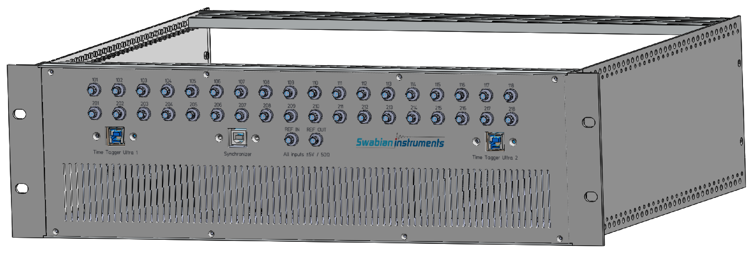
Rack mount for up to two Time Tagger Ultra and one Synchronizer
Parameter |
Value |
|---|---|
Channels |
Up to 18 with one Time Tagger Ultra installed Up to 36 with two Time Tagger Ultra installed |
Height units |
3 |
Depth |
37 cm |
Weight without devices |
3.5 kg |
Please get in touch with sales@swabianinstruments.com for additional information.
Time Tagger 20
Swabian Instruments doesn’t provide an option to mount the Time Tagger 20 in a 19-inch rack.